MultiSite ACI Fabric project design with Nexus Dashboard Orchestrator best-practices
08.03 2022 | by massimilianoIl presente documento ricopre un ruolo di LLD (Low Level Design) per la realizzazione di un progetto MultiSite attraverso best-practices […]
https://www.ingegnerianetworking.com/wp-content/uploads/2022/03/msite-design-a38.png
Il presente documento ricopre un ruolo di LLD (Low Level Design) per la realizzazione di un progetto MultiSite attraverso best-practices Cisco ACI.
La release ACI APIC di riferimento è la 4.2(4i).
La release degli Switch Nexus Fabric è la 14.2(4i)
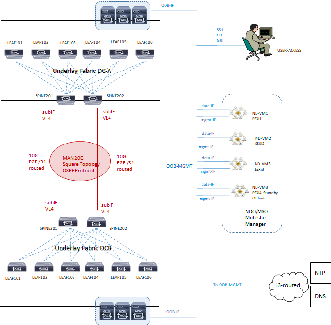
L’architettura di riferimento è la seguente:
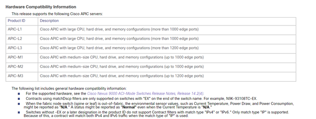
1) Hardware Compatibility Information:
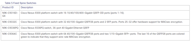
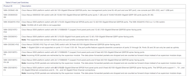
2) Spine and Leaf Compatibility:
SPINE:
LEAF:
3) MSO/NDO best-practices:
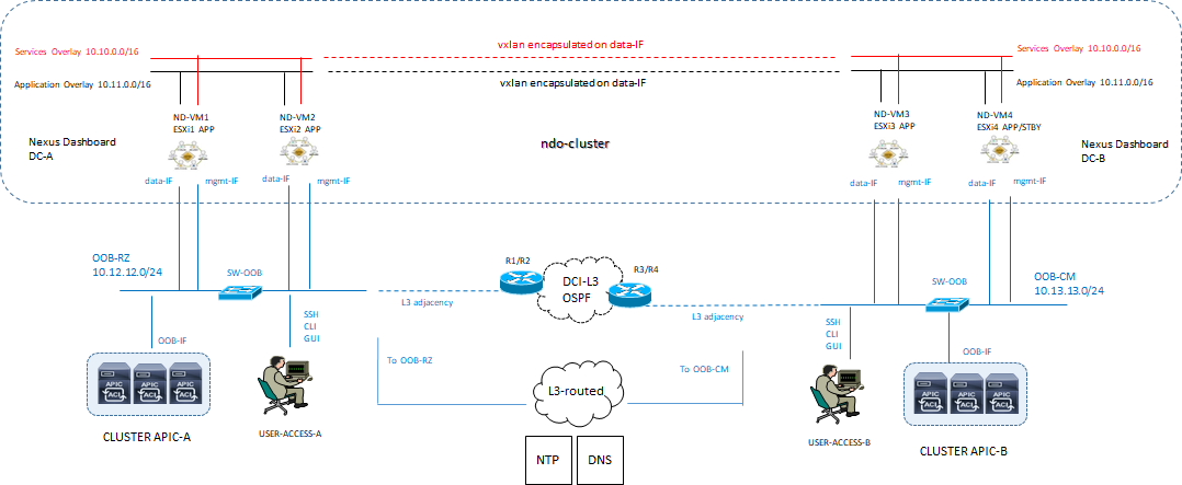
Il sistema MSO e/o NDO (Nexus Dashboard Orchestrator) rappresenta la consolle centrale di management inter-site datacenter.
Ciascun Nexus Dashboard cluster consiste di n° 3 nodi master; per la versione fisica Nexus dashboard cluster sono anche previsti worker nodes per motivi di scalabilità orizzontale e standby nodes per motivi di recovery in caso di faults master node, mentre per la versione virtuale cloud-cluster solo n° 3 nodes sono supportati.
MSO/NDO non sostituisce la funzione APIC il quale mantiene la gestione ed il controllo della sua Fabric di pertinenza.
MSO/NDO è responsabile di provvedere e gestire inter-site (anche detto traffic east-west) tenant e policies di rete per poi andare a propagare queste verso i rispettivi cluster APIC Fabric ACI.
Requisiti in riferimento alla all’ultima versione Nexus Dashboard 2.1.1 e NDO 3.5.x
- NDO è un’applicazione a Container che gira su un cluster Kubernetes “Cisco” incluso nella Nexus Dashboard come hosted application; per l’installazione della Nexus dashboard che è un pre-requisito di NDO è necessario soddisfare i seguenti steps:
- NTP server per il clock-synchonization;
- External Network ND:
- Data Network per la comunicazione tra nodi NDO ed APIC cluster;
- Management Network per accesso in GUI/CLI/SSH, DNS e NTP communication, NDO firmware upload, intersight device connector
- Raggiungibilità rete di management OOB sistema APIC cluster dalla Data Network;
- Internal Network ND: due reti supplementari sono necessarie per la comunicazione tra containers utilizzati nel Nexus Dashboard
- Una rete /16 come application overlay pre-popolata durante il deploy;
- Una rete /16 come service overlay pre-popolata durante il deploy;
NOTA: è best-practices che le due reti di cui sopra per la comunicazione del ND cluster siano univoche e differenti dalle reti clienti.
Nexus Dashboard supporta una configurazione di nodi in siti differenti.
Il nodo standby è supportato solo nella versione di ND physical appliance e pertanto nella versione virtualizzata se un nodo fallisce, vi è la necessità di portare UP un nuovo virtual node per sostituire quello in fault.
La comunicazione tra containers rilasciati in differenti Nexus dashboard è VXLAN-encapuslated attraverso data interface IP address source e destination; questo significa che le reti application e services non devono mai essere esposte al di fuori della Data network e qualsiasi subnets è ruotata internamente al cluster.
NOTA: I nodi del cluster, se ospiteranno solo MSO/NDO come applicazione, possono essere distribuiti su subnet/siti diversi (non necessitano di essere adiacenti a livello 2).
È raccomandata la disponibilità di un nodo standby sul sito dove è presente un solo master node per mantenere il cluster operativo in caso di indisponibilità del sito con due master.
NOTA: Se abbiamo la necessità di utilizzare altre applicazioni come Nexus Insights allora si dovrà creare un altro cluster su un solo sito.
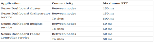
- Il massimo valore di RTT tra VM in cluster deve essere minore di 150 ms;
- La massima distanza tra il cluster MSO ed APIC Fabric non deve superare il valore di 1 sec RTT;
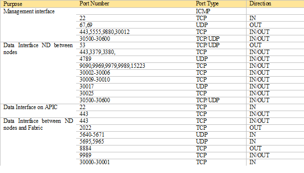
- Abilitare le seguenti porte utilizzate dal Nexus dashboard cluster:
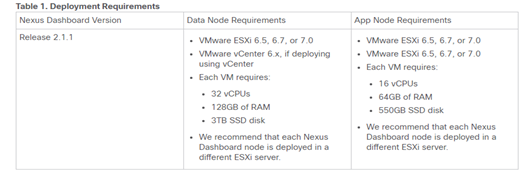
4) Deploy NDO VMware best-practices:
- ESXi 6.5, 6.7, or 7.0,
- ogni VM richiede: 16 vCPUs, 64GB of RAM, 550GB SSD disk
NOTA CISCO:
- Data Node—node profile designed for data-intensive applications, such Nexus Dashboard Insights
- App Node—node profile designed for non-data-intensive applications, such Nexus Dashboard Orchestrator
- After each node’s VM has deployed, ensure that the VMware Tools periodic time synchronization has disabled as described in the deployment procedure.
- VMware Distributed Resource Scheduler (DRS) has not supported for Nexus Dashboard cluster nodes.
- You can choose to deploy the nodes directly in ESXi or using vCenter.
- If you want to deploy using vCenter, following the steps described in Deploying Cisco Nexus Dashboard Using VMware vCenter.
- If you want to deploy directly in ESXi, following the steps described in Deploying Cisco Nexus Dashboard Directly in VMware ESXi.
Le principali funzioni del sistema MSO/NDO sono:
- Gestione di regole di accesso attraverso RBAC (Role Based Access Control);
- L’aggiunta, la cancellazione e la modifica di ACI sites;
- L’impiego della dashboard per la verifica dello stato in termini di health, fault e logs per tutte le inter-site policies che sono parte del dominio ACI Fabric;
- Provisionig day-0 che permette il collegamento ed il peering tra Spine dei due site datacenter; questa capacità prevede l’abilitazione del protocollo MP-BGP control-plane e lo scambio di informazioni host-endpoint (MAC + IPv4 addresses)
- Creazione di Tenant con il rilascio di questi nei due site datacenter;
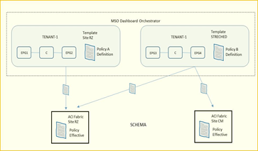
- Definizione di policies template ed associazione di esse ai due site datacenter; le best-practices Cisco raccomandano di gestire tutte le configurazioni per tutti i tenant (object EPG, BD, VRF, Contract) direttamente dal sistema MSO indipendentemente dal fatto che questi oggetti siano streched lungo i due site oppure specifici per un determinato site.
NOTA: la definizione di “Container” è indicata per uno o più policies-template raggruppati insieme e parte di uno schema; l’associazione di policies di un determinato tenant è comunque sempre definito a livello tenant, non schema.
È necessario per il supporto tra MSO ed ACI una compatibilità tra le rispettive versioni in relazione ai cluster APIC; una connessione “websocket” è impiegata tra il sistema MSO ed ogni APIC registrato in MSO la cui funzione è quella di essere sempre a conoscenza attraverso specifiche query da parte del MSO quando un APIC va in down e poi torna up (caso ad esempio di un APIC upgrade)
La seguente tabella mette in evidenza le funzionalità ACI in relazione alla minima versione APIC supportata:
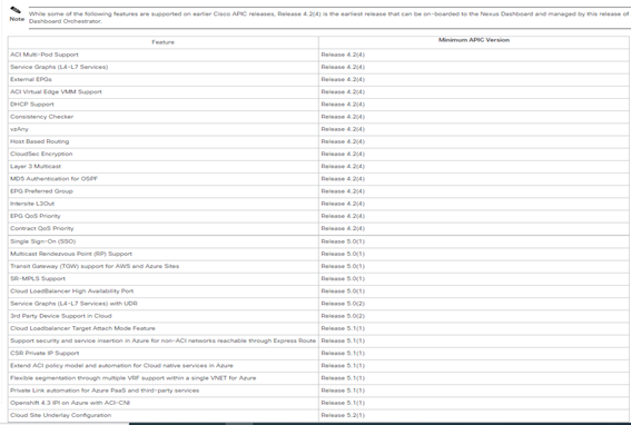
NOTA: MSO operante come as-a-services dashboard NDO, la versione minima ACI release Fabric onboard ND deve essere la 4.2(4).
MSO utilizza due metodi per verifica la versione di un APIC:
- Durante il “save” di un operation template e questo è importante ai fini di stabilire la compatibilità tra la configurazione eseguita con la versione software APIC;
- Con il “deploy” di un template; questo è richiesto nel caso si voglia rilasciare un template senza prima eseguirne il salvataggio.
5) Fabric Connectivity:
Il sistema Nexus dashboard cluster viene collegato in uno di questi due modi:
- ND cluster collegato alla Fabric via layer 3 (raccomandato da best-practices)
- ND cluster collegato ai nodi leaf;
I requisiti per l’installazione NDO 3.5(1) sono relativi alla versione di Nexus Dashboard che deve essere 2.1.1 o successiva ed ai modelli di switch spine e leaf che devono supportare il multisite.
NOTA: la prima generazione di Nexus 9000 non supporta il multisite;
Il link cisco riporta la compatibility matrix: Cisco ACI-mode Switches Hardware SupportMatrix
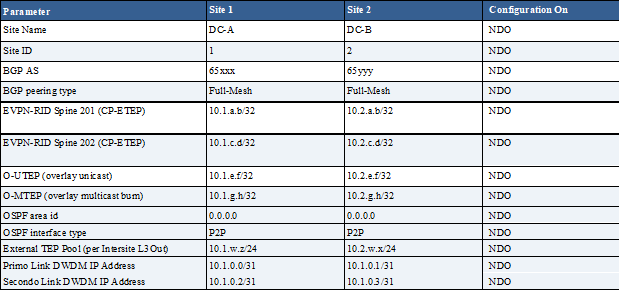
6) Virtual Form Factor and IP addressing Plan:
Per il progetto multisite vengono indicati i passi seguenti di configurazione e piano di indirizzamento necessari:
- Creazione di un cluster di n° 4 virtual machine ESXi .ova (tre master ed uno offline)
- Indirizzo IP NTP
- DC-A = 10.b.c.d
- DC-B = 10.e.f.g
- Indirizzo IP DNS
- DC-A = 10.h.l.m
- DC-B = 10.n.o.p
- Domain Name = client.msite.lan
- External Network ND
- Management OOB network IP subnet
- DC-A = 10.12.12.0/24
- DC-B = 10.13.13.0/24
- Internal Network ND Cluster
- Services Overlay = 10.10.0.0/16
- Application Overlay = 10.11.0.0/16
Best Practices Cisco:
- Le due reti possono coesistere o meno all’interno di una stessa subnet, seppur le best-practice raccomandano due subnet differenti come previsto da questo progetto;
- Ogni network interface tra differenti nodi ND in cluster possono essere in subnet differenti come previsto in questo progetto; le uniche eccezioni sono riportate di seguito:
- Nexus Dashboard Insights service con DCNM Fabric i nodi debbono essere layer 2 adjacent per la DATA network e deve essere utilizzato sFlow oppure NetFlow (non previsto da questo progetto)
- Nexus Dashboard Fabric Connector services, la DATA e MGMT network debbono essere su differenti subnets e le rispettive interfaces debbono essere L2 adjacent (non previsto da questo progetto)
- Per cluster di tipo fisico (non previsto da questo progetto) la MGMT network deve prevedere raggiungibilità di ogni nodo via CIMC TCP ports 22/443; ND cluster configuration utilizza per ogni nodo la CIMC IP address.
- Nexus Dashboard Orchestrator (NDO) service la DATA network può avere in-band oppure out-of-band IP raggiungibilità per i Cisco APIC cluster, ma deve avere solo in-band raggiungibilità per Cisco DCNM (Data Center Network Manager) sites.
NOTA: DCNM è una piattaforma offerta da Cisco per automazione e controllo per la gestione della Fabric Spine/Leaf non prevista in questo progetto.
- DATA network interface richiede un MTU = minimum 1500;
- La connettività tra nodi è un requisito con i seguenti valori di RTT (round-trip time)
7) Nexus Dashboard Setup Upgrade Software (from Cisco):
STEP-1:
Download the Nexus Dashboard image.
- Browse to the Software Download page (from software/cisco/download link)
Download the Cisco Nexus Dashboard image nd-dk9.2.1.1e.iso
- When you upload the image to your Nexus Dashboard cluster, you will have an option to provide a direct URL to the image.
STEP-2:
Log in to your current Nexus Dashboard GUI as an Administrator user.
STEP-3:
Upload the new image to the cluster.
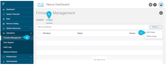
- Navigate to Operations > Firmware Management.
- Select the Images
- From the Actionsmenu, select Add Image.
STEP-4:
Select the new image.
- In the Add Firmware Image window, select Local.
Alternatively, if you hosted the image on a web server, choose Remote instead.
- Click Select file and select the ISO image you downloaded in the first step.
If you chose to upload a remote image, provide the file path for the image on the remote server.
- Click Upload to add the image.
The image will be uploaded to the Nexus Dashboard cluster, unpacked, processed, and made available for the upgrade.
The whole process may take several minutes and you will be able to see the status of the process in the Images tab.
STEP-5:
Wait for the image status to change to Downloaded.
You can check the status of the image download progress in the Images.
STEP-6:
Setup the update.
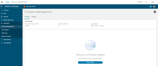
- Navigate to Operations > Firmware Management.
- Select the Updates
- Click Setup Update.
The Firmware Update screen opens.
STEP-7:
Choose the upgrade image.
- In the Firmware Update > Version selection screen, select the firmware version you uploaded and click Next.
- In the Firmware Update > Confirmationscreen, verify the details and click Begin Install.
The installation progress window is displayed. You can navigate away from this screen while the update is in progress.
To check on the update status at a later time, navigate to the Firmware Management screen and click View Details in the Last Update Status tile.
This will set up the required Kubernetes images and services but will not switch the cluster to the new version. The cluster will continue to run the existing version until you activate the new image in the next step.
The entire process may take up to 20 minutes.
STEP-8:
Activate the new image.
- Navigate back to the Operations > Firmware Management screen
- In the Last Update Status tile, click View Details.
- Click Activate.
- In the Activation Confirmation window, click Continue.
It may take up to 20 additional minutes for all the cluster services to start and the GUI to become available. The page will automatically reload when the process is completed.
STEP-9:
If you upgraded a virtual cluster deployed in VMware ESX, convert the nodes to the new profile.
|
Note |
If you upgraded a physical cluster, skip this step. |
Starting with Release 2.1(1), Nexus Dashboard supports two different node profiles for virtual nodes deployed in VMware ESX. After the upgrade, you must convert all the nodes of the existing cluster to one of the new profiles:
- Data node—node profile designed for data-intensive applications, such as Nexus Dashboard Insights
- App node—node profile designed for non-data-intensive applications, such as Nexus Dashboard Orchestrator
The profile you choose depends on your use case scenario:
- If you plan to run only the Nexus Dashboard Orchestrator service, convert all nodes to the Appnode profile (nostro caso)
- If you plan to run Nexus Dashboard Insights or co-host applications, you must convert the nodes to the Data
You convert the nodes to the new profile by deploying brand new nodes using that profile and replacing existing nodes with them one at a time.
- Bring down one of the nodes.
You must replace one node at a time.
- Deploy a new node in VMware ESX using the Appfile nd-dk9.2.1e-app.ova
When deploying the new node, you must use the same exact network configuration parameters as the node you are replacing. You must also ensure that the Cluster Leader checkbox in the OVF parameters is left unchecked.
- Log in to the existing Nexus Dashboard GUI.
You can use the management IP address of one of the remaining healthy master nodes.
- From the left navigation pane, select System Resources > Nodes.
The node you are replacing will be listed as Inactive.
- Click the (…) menu next to the inactive master node you want to replace and select Replace.
The Replace window will open.
- Provide the Management IP Addressand Passwordfor the node, then click Verify.
The cluster will connect to the new node’s management IP address to verify connectivity.
- Click Replace.
It may take up to 20 minutes for the node to be configured and join the cluster.
- Wait for the cluster to become healthy, then repeat this step for the other two nodes.
STEP-10:
If you are hosting multiple applications in the same cluster, configure deployment profiles for the App Infra Services.
If you are hosting only a single application in your Nexus Dashboard cluster, skip this step.
If you are co-hosting multiple applications in the same cluster, you must configure the App Infra Services with deployment profiles appropriate for your combination of applications and fabric sizes.
8) Nexus Dashboard Adding Site (from Cisco)
STEP-1:
Log in to the Nexus Dashboard GUI
STEP-2:
Add a new site
- From the left navigation menu, select Sites.
- In the top right of the main pane, select Actions> Add Site.
STEP-3:
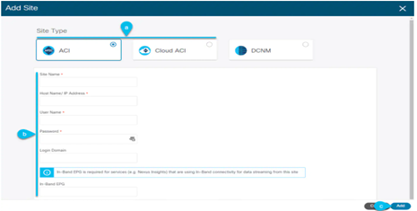
Provide site information
- For Site Type, select ACIor Cloud ACIdepending on the type of ACI fabric you are adding.
- Provide the controller information.
You need to provide the Host Name/IP Address, User Name, and Password for the APIC controller currently managing your ACI fabrics.
|
Note |
For APIC fabrics, if you will use the site with Nexus Dashboard Orchestrator service only, you can provide either the in-band or out-of-band IP address of the APIC. If you will use the site with Nexus Dashboard Insights as well, you must provide the in-band IP address. |
For on-premises ACI sites managed by Cisco APIC, if you plan to use this site with Day-2 Operations applications such as Nexus Insights, you must also provide the In-Band EPG name used to connect the Nexus Dashboard to the fabric you are adding. Otherwise, if you will use this site with Nexus Dashboard Orchestrator only, you can leave this field blank.
- Click Add to finish adding the site.
At this time, the sites will be available in the Nexus Dashboard, but you still need to enable them for Nexus Dashboard Orchestrator management as described in the following steps.
STEP-4:
Repeat the previous steps for any additional ACI sites.
STEP-5:
From the Nexus Dashboard’s Service Catalog, open the Nexus Dashboard Orchestrator service.
You will be automatically logged in using the Nexus Dashboard user’s credentials.
STEP-6:
In the Nexus Dashboard Orchestrator GUI, manage the sites
- From the left navigation menu, select Infrastructure > Sites.
- In the main pane, change the State from Unmanagedto Managed for each fabric that you want the NDO to manage.
9) Nexus Dashboard installing manually (from Cisco)
STEP-1:
Download the Cisco Nexus Dashboard Orchestrator service.
File: Cisco-MSO-3.5.1e.aci
- Browse to the Nexus Dashboard Orchestrator download page:
From the left navigation menu, select the 3.5.1 release
- Click the download icon next to the .nap
- Click Agree and download to accept the license agreement and download the image.
STEP-2:
Log in to your Cisco Nexus Dashboard dashboard.
When deploying an app, you need to install it in only one of the Nexus Dashboard nodes, the application will be replicated to the other nodes in the cluster automatically. So you can log in to any one of your Nexus Dashboard nodes using its management IP address.
STEP-3:
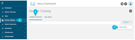
Upload the app image.
- In the left navigation bar, click Service Catalog.
- Select the Installed Services
- In the top right of the main pane, select Actions > Upload App.
STEP-4:
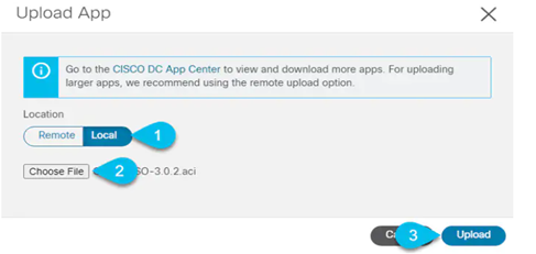
Upload the image file to the Nexus Dashboard cluster
- Choose the location of the image.
If you downloaded the application image to your system, choose Local.
If you are hosting the image on a server, choose Remote.
- Choose the file.
If you chose Local in the previous substep, click Select File and select the app image you downloaded.
If you chose Remote, provide the full URL to the image file, for example http://<ip-address>:<port>/<full-path>/cisco-mso-<version>.aci.
- Click Upload to add the app to the cluster.
STEP-5:
Wait for the application to be downloaded to the Nexus Dashboard and deployed.
It may take up to 30 minutes for the application to replicate to all nodes and all services to fully deploy.
STEP-6:
Enable the app.
After installation is complete, the application will remain in the Disabled state by default and you must enable it.
To enable the app, click the … menu on the app and select Enable.
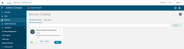
STEP-7:
Launch the app.
To launch the app, simply click Open on the application tile in the Nexus Dashboard’s Service Catalog page; the single sign-on (SSO) feature allows you to log in to the application using the same credentials as you used for the Nexus Dashboard.
10) Nexus Dashboard day-0 configuring ACI site (from Cisco):
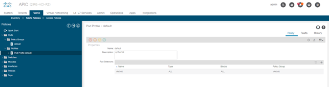
POD PROFILE and POLICY GROUP (on APIC site):
STEP-1:
Check that the Pod profile contains a Pod policy group.
Navigate to Fabric > Fabric Policies > Pods > Profiles > Pod Profile default.
STEP-2:
If necessary, create a Pod policy group.
- Navigate to Fabric> Fabric Policies> Pods > Policy Groups.
- Right-click Policy Groupsand select Create Pod Policy Group.
- Enter the appropriate information and click Submit.
STEP-3:
Assign the new Pod policy group to the default Pod profile.
- Navigate to Fabric> Fabric Policies> Pods > Profiles > Pod Profile default
- Select the default profile.
- Choose the new pod policy group and click Update.
“Lasciare il POD default “
CONFIG FABRIC ACCESS GLOBAL POLICIES (on APIC site):
STEP-4:
From the main navigation menu, select Fabric > Access Policies.
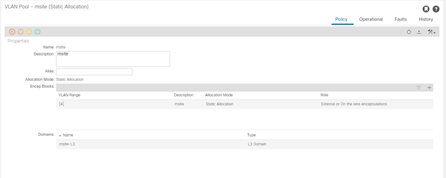
Specify the VLAN pool.
The first thing you configure is the VLAN pool. We use Layer 3 sub-interfaces tagging traffic with VLAN-4 to connect the spine switches to the inter-site network.
- In the left navigation tree, browse to Pools > VLAN.
- Right-click the VLAN category and choose Create VLAN Pool.
In the Create VLAN Pool window, specify the following:
- For the Name field, specify the name for the VLAN pool
- For Allocation Mode, specify Static Allocation.
- And for the Encap Blocks, specify just the single VLAN 4. You can specify a single VLAN by entering the same number in both Range
STEP-6:
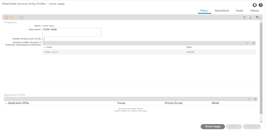
Configure Attachable Access Entity Profiles (AAEP).
- In the left navigation tree, browse to Global Policies > Attachable Access Entity Profiles.
- Right-click the Attachable Access Entity Profilescategory and choose Create Attachable Access Entity Profiles.
In the Create Attachable Access Entity Profiles window, specify the name for the AAEP
- Click Next and Submit
No additional changes, such as interfaces, are required.
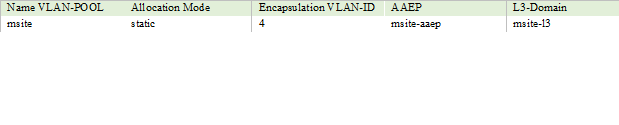
STEP-7:
Configure domain.
The domain you configure is what you will select from the Nexus Dashboard Orchestrator when adding this site.
- In the left navigation tree, browse to Physical and External Domains > External Routed Domains.
- Right-click the External Routed Domains category and choose Create Layer 3 Domain.
In the Create Layer 3 Domain window, specify the following:
- For the Name field, specify the name the domain,
- For Associated Attachable Entity Profile, select the AEP you created in Step 6.
- For the VLAN Pool, select the VLAN pool you created in Step 5.
- Click Submit.
No additional changes, such as security domains, are required.
CONFIG FABRIC ACCESS INTERFACE POLICIES (on APIC site):
STEP-8:
From the main navigation menu, select Fabric > Access Policies.
In addition to the VLAN, AEP, and domain you have configured in previous section, you must also create the interface policies for the fabric’s spine switch interfaces that connect to the Inter-Site Network (ISN).
STEP-9:
Configure a spine policy group.
- In the left navigation tree, browse to Interface Policies > Policy Groups > Spine Policy Groups.
This is similar to how you would add a bare-metal server, except instead of a Leaf Policy Group, you are creating a Spine Policy Group.
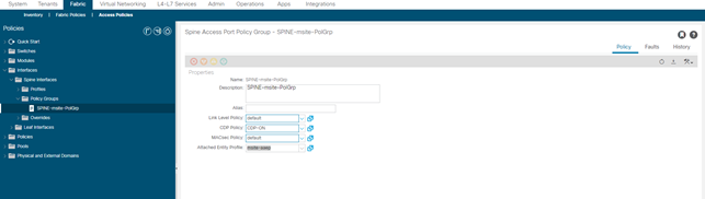
- Right-click the Spine Policy Groups category and choose Create Spine Access Port Policy Group.
In the Create Spine Access Port Policy Group window, specify the following:
- For the Name field, specify the name for the policy group
- For the Link Level Policy field, specify the link policy used between your spine switch and the ISN.
- For CDP Policy, choose whether you want to enable CDP.
- For the Attached Entity Profile, select the AEP you have configured in previous section
- Click Submit.
No additional changes, such as security domains, are required.
STEP-10:
Configure a spine profile.
- In the left navigation tree, browse to Interface Policies > Profiles > Spine Profiles.
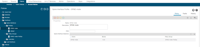
- Right-click the Spine Profiles category and choose Create Spine Interface Profile.
In the Create Spine Interface Profile window, specify the following:
- For the Name field, specify the name for the profile,
- For Interface Selectors, click the + sign to add the port on the spine switch that connects to the ISN. Then in the Create Spine Access Port Selector window, provide the following:
- For the Name field, specify the name for the port selector
- For the Interface IDs, specify the switch port that connects to the ISN, for example 1/33.
- For the Interface Policy Group, choose the policy group you created in the previous step
Then click OK to save the port selector.
- Click Submit to save the spine interface profile.
STEP-11:
Configure a spine switch selector policy.
- In the left navigation tree, browse to Switch Policies > Profiles > Spine Profiles.
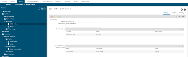
- Right-click the Spine Profiles category and choose Create Spine Profile.
In the Create Spine Profile window, specify the following:
- For the Name field, specify the name for the profile,
- For Spine Selectors, click the + to add the spine and provide the following:
- For the Name field, specify the name for the selector
- For the Blocks field, specify the spine node, for example 201-202.
- Click Update to save the selector.
- Click Next to proceed to the next screen.
- Select the interface profile you have created in the previous step
For example Spine-ISN.
- Click Finish to save the spine profile.
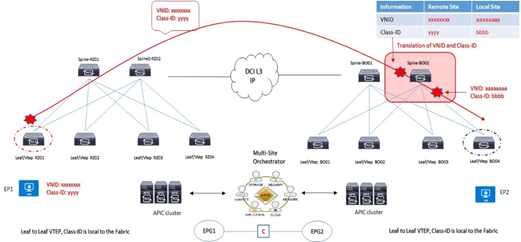
INTERSITE B2B MULTISITE ON-BOARDING
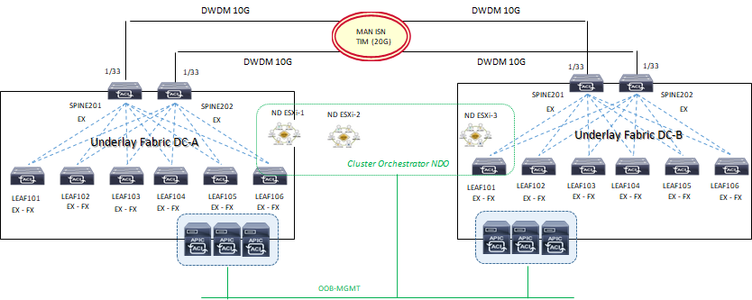
L’architettura considerata per il collegamento tra i due siti datacenter è quella di tipo back-to-back Spine.
Questa tipologia è consentita a partire dalla ACI release 3.2(1)
Il sistema ND/NDO è requisito per la configurazione delle policies inter-site eppoi essere applicate ai rispettivi cluster APIC.
- Un L3-out interface deve essere definito come infra-tenant specificando gli Spine nodes e le interfacce coinvolte per la soluzione B2B;
- Un internal TEP pool deve essere definito ed assegnato per remote site;
- Un external TEP pool deve essere definito ed assegnato ad ogni site; questo external pool provvede per il forwarding data-plane TEP-IP impiegato per il MP-BGP EVPN inter-site; questo stesso pool è utilizzato per assegnare un anycast TEP per ogni site.
NOTA:
Control-Plane BGP: mantenere i valori di keepalive-interval (sec), hold-interval (sec), stale-interval (sec) di default e Graceful-Helper enable.
Best-Practices B2B intersite:
- Solo due Fabric site sono permessi essere collegati; la soluzione hybrid è consentita ma fuori scope da questo progetto.
- L’architettura a quadrato (square) è permessa considerando comunque una configurazione full-mesh BGP tra Spine; da considerare comunque che per il traffico BUM inter-site, questi è sempre originato da uno specifico Spine eletto come come designated-forwarder per un determinato Bridge Domain e destinato verso il O-MTEP address. Il ricevente Spine ritrasmetterà poi il traffico BUM internamente al suo site (non vi è elezione designated-forwarder lato site ricevente).
- Collegare i due link DWDM 10G ai rispettivi Spine ACI Fabric;
- MACsec encryption abilitato per un traffico sicuro inter-site communication (requisito non essenziale e non configurato soprattutto su un ambiente DWDM)
Gli Spine inter-site debbono essere direttamente collegati fisicamente o logicamente e questo significa che una infrastruttura di tpo layer 2 non è consentita ed il solo impiego di link dark-fiber o DWDM è consentito;
- L’utilizzo di EoMPLS pseudowire è possibile in modo da rendere compatibile una soluzione P2P tra gli Spine attraverso una rete MPLS core network;
- Il solo collegamento possibile L3-out back-to-back è di tipo “infra-tenant” con la configurazione via MSO applicata ai rispettivi cluster APIC per un corretto forwarding in termini di VNI, Class-ID translation su Spine inter-site.
- Almeno uno Spine con soluzione b2b inter-site deve avere un link attivo con LLDP (leaf-facing link)
Una funzionalità chiamata “Namespase Normalisation“ prevede un piano di fordwarding Multi-Site attraverso determinati field definiti in VNID, Class-ID associati ad un specifico tenant packet.
Mantenimento separato di name spaces con ID tradotto a livello di Spine Nodes
- È richiesto un hardware dedicato agli Spine per supportare questa funzionalità
- MSO/NDO istruisce gli APIC cluster per programmare la traduzione nelle tabelle di forwarding degli Spine
NOTA:
VXLAN VNID = Network information carried across Fabrics (availability zones): identifica un Bridge Domain per comunicazioni layer 2 oppure VRF forwarding per comunicazioni layer 3 di un endpoint oppure un insieme di endpoint sorgenti di traffico
Class-ID = Identity information carried across Fabrics (availability zones): questo valore identifica un gruppo EPG sorgenti di traffico ed hanno significato locale solo all’interno della propria Fabric di competenza.
- Configure day-0 infra-policies
- Select spines establishing MP-BGP EVPN peering with remote sites
- Site Overlay Unicast and Multicast TEP (O-UTEP and O-MTEP)
- Spine MP-BGP EVPN Router-ID (EVPN-RID)
OSPF è utilizzato per la raggiungibilità dei nodi spine con lo scambio di indirizzi TEP ed utilizza sub-interface con vlan-tag 4 verso i rispettivi Spine.
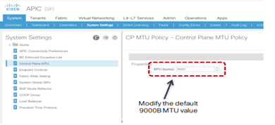
MTU value:
Data Plane MTU: l’MTU generato da endpoint (server, router, service node, etc..) collegati ai Leaf node necessita un overhead di 50/54 Bytes di VXLAN encapsulation per inter-site communication
Control Plane MTU: per traffico quale EVPN inter-site si necessità di un valore di default pari a 9000B; il tuning può essere fatto su base “CP MTU Policy” attraverso APIC
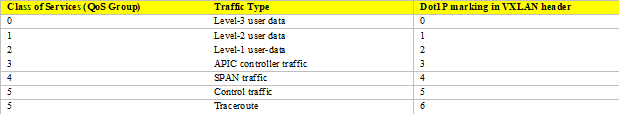
QoS value:
ACI Fabric supporta sei classi di servizio ed il traffico è classificato solo a livello ingress-leaf.
Ogni classe è configurata a livello Fabric e mappata in una coda hardware.
MP-BGP intersite peers:
Gli Spine hanno la funzione di stabilire sessioni MP-BGP EVPN tra loro con un dedicato control-plane addressing configurato si ciascun Spine coinvolto.
A livello data plane inter-site due tipologie di traffico sono configurate:
- Anycast Overlay Unicast TEP (O-UTEP) address è assegnato agli Spine tra loro connessi per ricevere L2/L3 traffic unicast;
- Anycast Overlay Multicast TEP (O-MTEP) address è assegnato agli Spine tra loro connessi per ricevere L2 BUM traffic.
Questo piano di indirizzamento è configurabile via NDO orchestrator e deve essere ruotabile via ISN.
MP-BGP EVPN è il protocollo con il quale ciascun endpoint è in grado di comunicare e scambiare informazioni con altri endpoint inter-site; è supportato sia la versione IBGP che EBGP.
Remote host route entries (EVPN type-2) sono associate ad un remote site Anycast O-UTEP address e vi è uno scambio di host-routes solo in presenza di un contratto tra EPG.
Esempi di verifica:
spine202# show ip ospf neighbors vrf all
spine202# show int eth1/33.33
spine202# show bgp l2vpn evpn summary vrf all
spine202# show bgp sessions vrf all
spine202# show bgp l2vpn evpn neighbors 10.2.2.3 advertised-routes vrf all
11) Nexus Dashboard Orchestrator day-0 configuring Infra General Setting (From Cisco)
La parte Infra Configuration evidenzia un overview dei site da gestire contenente le seguenti informazioni:
- General Settings riguardo il protocollo BGP peering e relativa configurazione;
- On-Premises evidenzia informazioni dei site facenti parte della topologia multisite domain con i numeri di Pods e Spine switches, OSPF settings e Overlay IPs;
STEP-1:
Log in to the Cisco Nexus Dashboard Orchestrator GUI.
STEP-2:
In the left navigation menu, select Infrastructure > Infra Configuration;
In the main pane, click Configure Infra;
In the left sidebar, select General Settings.
STEP-3:
Provide Control Plane Configuration.
- Select the Control Plane Configuration
- Choose BGP Peering Type.
- full-mesh—All border gateway switches in each site will establish peer connectivity with remote sites’ border gateway switches.
In full-mesh configuration, Nexus Dashboard Orchestrator uses the spine switches for ACI managed fabrics and border gateways for DCNM managed fabrics (riferito al nostro progetto)
- route-reflector—The route-reflector option allows you to specify one or more control-plane nodes to which each site establishes MP-BGP EVPN sessions. The use of route-reflector nodes avoids creating MP-BGP EVPN full mesh
- adjacencies between all the sites managed by NDO (non riferito al nostro progetto ma riportato qui per completezza di informazione tecnica)
For ACI fabrics, the route-reflector option is effective only for fabrics that are part of the same BGP ASN.
- In the Keepalive Interval (Seconds) field, enter the keep alive interval seconds.
We recommend keeping the default value.
- In the Hold Interval (Seconds) field, enter the hold interval seconds.
We recommend keeping the default value.
- In the Stale Interval (Seconds) field, enter stale interval seconds.
We recommend keeping the default value.
- Choose whether you want to turn on the Graceful Helper
- Provide the Maximum AS Limit.
We recommend keeping the default value.
- Provide the BGP TTL Between Peers.
We recommend keeping the default value.
- Provide the OSPF Area ID.
If you do not have any Cloud APIC sites, this field will not be present in the UI.
This is OSPF area ID used by cloud sites for on-premises IPN peering, which you previously configured in the Cloud APIC for inter-site connectivity in earlier Nexus Dashboard Orchestrator releases.
STEP-4:
Provide the IPN Devices information.
If you do not plan to configure inter-site connectivity between on-premises and cloud sites, you can skip this step.
When you configure inter-site underlay connectivity between on-premises and cloud sites as described in later sections, you will need to select an on-premises IPN device which will establish connectivity to the cloud CSRs.
These IPN devices must first be defined here before they are available in the on-premises site configuration screen, which is described in more detail in Configuring Infra: On-Premises Site Settings.
Select the IPN Devices tab.
- Click Add IPN Device.
- Provide the Nameand the IP Addressof the IPN device.
The IP address you provide will be used as the tunnel peer address from the Cloud APIC’s CSRs, not the IPN device’s management IP address.
- Click the check mark icon to save the device information.
- Repeat this step for any additional IPN devices you want to add.
CONFIG INFRA ON-PREMISES site (on NDO)
STEP-5:
In the left navigation menu, select Infrastructure > Infra Configuration;
In the main pane, click Configure Infra;
In the left pane, under Sites, select a specific on-premises site.
STEP-6:
Provide the Overlay Configuration.
- In the right <Site > Settings pane, select the Overlay Configuration
- In the right <Site> Settings pane, enable the Multi-Site
This defines whether the overlay connectivity is established between this site and other sites.
- (Optional) Enable the CloudSec Encryption knob encryption for the site.
CloudSec Encryption provides inter-site traffic encryption. The “Infrastructure Management” chapter in the Cisco Multi-Site Configuration Guide covers this feature in detail.
- Specify the Overlay Multicast TEP.
This address is used for the inter-site L2 BUM and L3 multicast traffic. This IP address is deployed on all spine switches that are part of the same fabric, regardless of whether it is a single pod or Multi-Pod fabric.
This address should not be taken from the address space of the original fabric’s Infra TEP pool or from the 0.x.x.x range.
- (Optional) From the External Routed Domain dropdown, select the domain you want to use.
Choose an external router domain that you have created in the Cisco APIC GUI. For more information, see the Cisco APIC Layer 3 Networking Configuration Guide specific to your APIC release.
- Specify the BGP Autonomous System Number.
- (Optional) Specify the BGP Password.
STEP-7:
Provide the Underlay Configuration.
The following settings are required if you are using OSPF protocol for underlay connectivity between the site and the IPN. If you plan to use BGP instead, you can skip this step.
BGP underlay configuration is done at the port level, as described in Configuring Infra: Spine Switches.
- In the right <Site> Settings pane, select the Underlay Configuration
- Provide the OSPF Area ID.
- Select the OSPF Area Type from the dropdown menu.
The OSPF area type can be one of the following:
- nssa
- regular
- Configure OSPF policies for the site.
You can either click an existing policy (for example, msc-ospf-policy-default ) to modify it or click +Add Policy to add a new OSPF policy. Then in the Add/Update Policy window, specify the following:
- In the Policy Name field, enter the policy name.
- In the Network Type field, choose either broadcast, point-to-point, or unspecified.
The default is broadcast.
- In the Priority field, enter the priority number.
The default is 1.
- In the Cost of Interface field, enter the cost of interface.
The default is 0.
- From the Interface Controls dropdown menu, choose one of the following:
- advertise-subnet
- bfd
- mtu-ignore
- passive-participation
- In the Hello Interval (Seconds) field, enter the hello interval in seconds.
The default is 10.
- In the Dead Interval (Seconds) field, enter the dead interval in seconds.
The default is 40.
- In the Retransmit Interval (Seconds) field, enter the retransmit interval in seconds.
The default is 5.
- In the Transmit Delay (Seconds) field, enter the transmit delay in seconds.
The default is 1.
While you have configured all the required inter-site connectivity information, it has not been pushed to the sites yet. You need to deploy the configuration as described in Deploying Infra Configuration
DEPLOYNG INFRA CONFIG (on NDO):
STEP-8:
In the top right of the main pane, click Deploy and choose the appropriate option to deploy the configuration.
If you have configured only on-premises or only cloud sites, simply click Deploy to deploy the Infra configuration.
However, if you have both, on-premises and cloud site, the following additional options may be available (non sono pertinenti al nostro progetto):
- Deploy & Download IPN Device Config files: Pushes the configuration to both the on-premises APIC site and the Cloud APIC site and enables the end-to-end interconnect between the on-premises and the cloud sites.
In addition, this option downloads a zip file that contains configuration information that you will use to enable connectivity from the IPN devices to Cisco Cloud Services Router (CSR). A follow up screen appears that allows you to select all or some of the configuration files to download.
- Deploy & Download External Device Config files: Pushes the configuration to both the Cloud APIC sites and enables the end-to-end interconnect between the cloud sites and external devices.
In addition, this option downloads a zip file that contains configuration information that you will use to enable connectivity from external devices to the Cisco Cloud Services Router (CSR) deployed in your cloud sites.
A followup screen appears that allows you to select all or some of the configuration files to download.
- Download IPN Device Config files only: Downloads a zip file that contains configuration information that you will use to enable connectivity from the IPN devices to Cisco Cloud Services Router (CSR) without deploying the
- configuration.
- Download External Device Config files only: Downloads a zip file that contains configuration information that you will use to enable connectivity from external devices to Cisco Cloud Services Router (CSR) without deploying the configuration.
STEP-9:
In the confirmation window, click Yes.
The Deployment started, refer to left menu for individual site deployment status message will indicate that Infra configuration deployment began and you can verify each site’s progress by the icon displayed next to the site’s name in the left pane.
CONFIG INFRA POD SETTINGS (on NDO)
STEP-10:
In the Main menu, click Sites;
In the Sites view, click Configure Infra;
In the left pane, under Sites, select a specific site;
In the main window, select a Pod.
STEP-11:
In the right Pod Properties pane, add the Overlay Unicast TEP for the Pod.
This IP address is deployed on all spine switches that are part of the same Pod and used for sourcing and receiving VXLAN encapsulated traffic for Layer-2 and Layer-3 unicast communication.
STEP-12:
Click +Add TEP Pool to add an external routable TEP pool.
The external routable TEP pools are used to assign a set of IP addresses that are routable across the IPN to APIC nodes, spine switches, and border leaf nodes. This is required to enable Multi-Site architecture.
External TEP pools previously assigned to the fabric on APIC are automatically inherited by NDO and displayed in the GUI when the fabric is added to the Multi-Site domain.
STEP-13:
Repeat the procedure for every Pod in the site.
CONFIG INFRA SPINE SWITCHING SETTING (on NDO)
This section describes how to configure spine switches in each site for Cisco Multi-Site. When you configure the spine switches, you are effectively establishing the underlay connectivity between the sites in your Multi-Site domain by configuring connectivity between the spines in each site and the ISN.
Prior to Release 3.5(1), underlay connectivity was establishing using OSPF protocol. In this release however, you can choose to use OSPF, BGP (IPv4 only), or a mixture of protocols, with some sites using OSPF and some using BGP for inter-site underlay connectivity. We recommend configuring either OSPF or BGP and not both, however if you configure both protocols, BGP will take precedence and OSPF will not be installed in the route table.
STEP-14:
In the Main menu, click Sites;
In the Sites view, click Configure Infra;
In the left pane, under Sites, select a specific site;
In the main window, select a spine switch within a pod;
In the right <Spine> Settings pane, click +Add Port.
STEP-15:
In the Add Port window, provide the underlay connectivity information.
Any port already configured directly in APIC for IPN connectivity will be imported and shown in the list. For any new ports you want to configure from NDO, use the following the steps:
- Provide general information:
- In the Ethernet Port IDfield, enter the port ID 1/33.
This is the interface which will be used to connect to the IPN.
- In the IP Address field, enter the IP address/netmask.
The Orchestrator creates a sub-interface with VLAN 4 with the specified IP ADDRESS under the specified PORT.
- In the MTU field, enter the MTU. You can specify either inherit, which would configure an MTU of 9150B, or choose a value between 576 and 9000.
MTU of the spine port should match MTU on IPN side.
- Configure OSPF settings if you want to use OSPF protocol for underlay connectivity.
If you want to use BGP protocol for underlay connectivity instead, skip this part and provide the information required in the next substep.
- Set OSPF to Enabled.
The OSPF settings will become available.
- From the OSPF Policy dropdown, select the OSPF policy for the switch that you have configured in Configuring Infra: On-Premises Site Settings.
OSPF settings in the OSPF policy you choose should match on IPN side.
- For OSPF Authentication, you can pick either non eor one of the following:
- MD5
- Simple
- Set BGP to Disabled.
- Configure BGP settings if you want to use BGP protocol for underlay connectivity.
If you’re using OSPF protocol for underlay connectivity and have already configured it in the previous substep, skip this part.
|
Note |
BGP IPv4 underlay is not supported in the following cases:
If your Multi-Site domain contains one or more Cloud APIC sites, in which case you must use the OSPF protocol for intersite underlay connectivity for both on-prem to on-prem and on-prem to cloud sites.
If you are using GOLF (Layer 3 EVPN services for fabric WAN) for WAN connectivity in any of your fabrics; in the above cases, you must use OSPF in the Infra L3Out deployed on the spines. |
- Set OSPF to Disabled.
We recommend configuring either OSPF or BGP and not both, however if you configure both protocols, BGP will take precedence and OSPF routes will not be installed in the route table because only EBGP adjacencies with the ISN devices are supported.
- Set BGP to Enabled.
The BGP settings will become available.
- In the Peer IP field, provide the IP address of this port’s BGP neighbor.
Only IPv4 IP addresses are supported for BGP underlay connectivity.
- In the Peer AS Number field, provide the Autonomous System (AS) number of the BGP neighbor.
This release supports only EBGP adjacencies with the ISN devices.
- In the BGP Password field, provide the BGP peer password.
- Specify any additional options as required:
- Bidirectional Forwarding Detection—enables Bidirectional Forwarding Detection (BFD) protocol to detect faults on the physical link this port and the IPN device.
- Admin State—sets the admin state on the port to enabled.
STEP-16:
Repeat the procedure for every spine switch and port that connects to the IPN.